
Foreword
1 Scope
2 Normative references
3 Terms and definitions
4 Product classification
5 Technical requirements
6 Test method
7 Inspection rules
8 Marking, packaging, transportation and storage
Foreword
In view of the current situation that the types, basic parameters and dimensions of special plugs, sockets and connectors for stage lighting have not yet unified international standards, we also take into account the fact that the equipment currently in use in China has a large variety, different specifications and poor safety. , Must set standards for it. This standard specifies the technical requirements, test methods, etc. of the types, basic parameters and dimensions of plug sockets and connectors for stage lighting in my country, and shall comply with the provisions of QB/T 2135-1995.
This standard is guided by GB/T 1.1-2000.
This standard was proposed by the Ministry of Culture of the People's Republic of China.
This standard was drafted by the Shanghai Stage Technology Research Institute, and participated in the drafting by the Shanghai Theatre Academy.
The main drafters of this standard: Shi Weicang, Liu Dean, Li Guoliang, Liu Liang.
People's Republic of China Cultural Industry Standard
Types, basic parameters and dimensions of single-phase three-pole plug sockets and connectors for stage lighting
1 Scope
This standard specifies the types, basic parameters and dimensions of single-phase three-pole plug sockets and connectors for stage lighting. This standard is applicable to plugs, sockets and connectors (hereinafter referred to as "electrical accessories") used in various power output, input and cable connections related to stage lighting. Its AC voltage does not exceed 250V and the frequency is 50Hz. The schematic diagram of electrical accessories is shown in Figure 1.
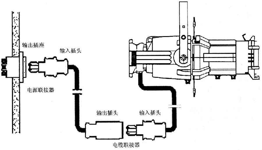
Figure 1 Schematic diagram of the use of electrical accessories
2 Normative references
The clauses in the following documents become the clauses of this standard through quotation from this standard. For dated reference documents, all subsequent amendments (not including errata content) or revisions do not apply to this section. However, parties to agreements based on this section are encouraged to study whether the latest versions of these documents can be used. For the cited documents without date, the latest version applies to this section.
GB 2423.3—1993 Basic environmental test procedures for electrical and electronic products Test ca: Constant damp heat test method
GB/T 2828-1987 Sampling procedure and sampling table for batch-by-batch inspection and counting
GB 4706.1—1998 Safety of household and similar electrical appliances Part 1 General requirements
QB/T 2135-1995 Technical conditions for single-phase three-pole plug sockets and connectors for film and television stage lamps
3 Terms and definitions
3.1 Power connector
Combination of output socket and input plug.
3.2 Cable connector
Combination of output plug and input plug.
3.3 Output socket
The output current is a socket composed of a plug-in type.
3.4 Input plug
Input current, a plug composed of a pin type, and connect the cable.
3.5 Output plug
Output current. A plug composed of a plug-in type and connected to a cable.
3.6 Holding device
Keep the output plug and input plug properly combined, and avoid the mechanical structure that is accidentally pulled out.
4 Product classification
4.1 The series specifications of electrical accessories shall comply with the provisions in Table 1.

4.2 The electrical accessories are ordinary plug connectors with grounding contacts and exchangeable wires.
4.3 Electrical accessories are divided into indoor and outdoor types.
5 Technical requirements
5.1 Appearance quality of electrical accessories
5.1.1 The appearance of thermosetting pressed plastic parts should be smooth and free of defects such as cracks, lack of material, deformation, scratches, burrs, etc.
5.1.2 The ferrous metal parts shall have an anti-corrosive protective layer, and the protective layer shall not have spots, lifting and peeling.
5.1.3 The surface of conductive parts should be smooth and free of burrs and corrosion marks.
5.1.4 There should be no loosening or automatic loosening at the screw connection.
5.2 Structure of electrical accessories
5.2.1 The fixing between the insulating shells of the separate plugs shall be pressed into the insulating material by the metal nut and connected with the metal screw. It must be removed with a tool to expose the live parts inside.
5.2.2 The insertion of electrical accessories can only be in one direction, and the ground electrode should be in contact before the conductive electrode, and when pulled out, it should be separated after the conductive electrode.
5.2.3 After the electrical accessories are wired and combined accordingly, the human body should not easily touch live parts.
5.2.4 The wire connector in the electrical accessories shall have a button-type holding device.
5.2.5 The pins in the electrical accessories should be fixed, but the sleeves can float.
5.2.6 The bolts, sockets, grounding electrodes and terminal blocks in the electrical accessories shall be made of copper or not less than 50% copper alloy.
5.3 Electrical accessories should be easy to insert and pull out, and their pull-out force should meet the requirements of Table 2.

5.4 Insulation resistance and dielectric strength of electrical accessories
5.4.1 Insulation resistance
After applying a DC voltage of 500 V for 1 min, its insulation resistance should be greater than 5 MΩ. All poles of the test site are connected together and measured between the body; alternately measured between each pole and other electrodes.
5.4.2 Dielectric strength
Use a frequency of 50Hz AC 2000V (2500V with a metal shell with an insulating pad) to carry out a pressure test of 1min.
There is no flicker and breakdown. The measurement location is that all the poles are connected together and between the body, and in turn between each pole and the other poles.
5.5 Temperature rise
Connect a cable with a cross-sectional area of not less than 2m in length according to Table 3 to the electrical accessories, and pass the 125% rated current for testing. The temperature rise of the conductive part and the grounding part shall not exceed 40°C.
5.6 The crimping plates on the plugs and connectors shall be made of insulating materials. When the cables specified in Table 3 are connected and tension is applied, the cable displacement shall not be greater than 2 mm.

5.7 There should be no risk of accidental contact between the ground terminal of the electrical accessory and the wire joint of the conductive terminal.
5.8 The socket of electrical accessories shall not be separated from the main body and be able to prevent electric shock when it bears 1.2 times the maximum pull-out force specified in Table 2.
5.9 Electrical accessories should have sufficient breaking capacity
The plug-to-socket or connector should be tested in accordance with 50 times of insertion and removal under 32A (including 32A). During the test, there should be no continuous arc jump. After the test, the sample should have no obvious damage to continue use.
5.10 Electrical accessories should be able to withstand the mechanical, electrical and thermal stresses that occur during normal use without excessive wear and other harmful effects. Insertion and removal frequency: 5000 times under 16A (including 16A), 2000 times under 32A, insert and pull once with current, insert and pull without current once, alternately.
5.11 Mechanical strength of electrical accessories
5.11.1 Impact test The spring impact device specified in Table 4 is used to impact the weakest point of the exposed part of the electrical accessory three times. After the test, the sample shall meet the following requirements.

a. Live parts should not become accessible;
b. There should be no cracks visible to the naked eye;
c. Does not reduce the leakage distance.
5.11.2 After 8 drop tests on the cable connector, there should be no loose parts.
5.12 The screws and nuts in the electrical accessories that play an electrical or mechanical connection shall be able to withstand the mechanical stresses that occur during normal use.
5.13 The creepage distance, electrical clearance and penetration insulation distance in electrical accessories shall not be less than those specified in Table 5.

5.14 Electrical accessories should be able to withstand the humid and hot conditions that may be encountered in normal use.
5.15 Electrical accessories should have sufficient heat resistance.
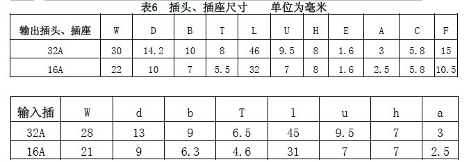
5.16 The types, basic parameters and dimensions of 16A and 32A electrical accessories shall comply with the provisions of Figures 2 to 4 and Table 6.
5.17 The cable must be crimped with a crimping head. Under normal use of electrical accessories, once the crimping screw is loose, it must not be detached from the conductive plate.
5.18 The protection grade of outdoor electrical accessories should not be lower than IP44.
6 Test method
Unless otherwise specified, the samples are tested at an ambient temperature of (20±5) °C (factory test at 5 °C ~ 35 °C) at the rated frequency, according to the delivery status and normal use conditions.
The accuracy of the electrical instruments used for testing is not less than 0.5 (except for the megohmmeter frequency meter), but the factory test can be used for 1.0, and the accuracy of the length measuring instrument is not less than 0.02mm.
The unit is mm
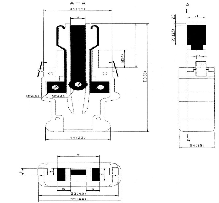 Figure 2 Input plug
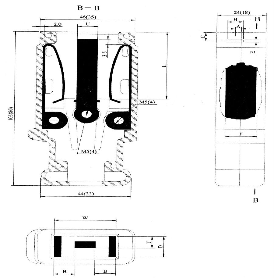
Figure 3 Input plug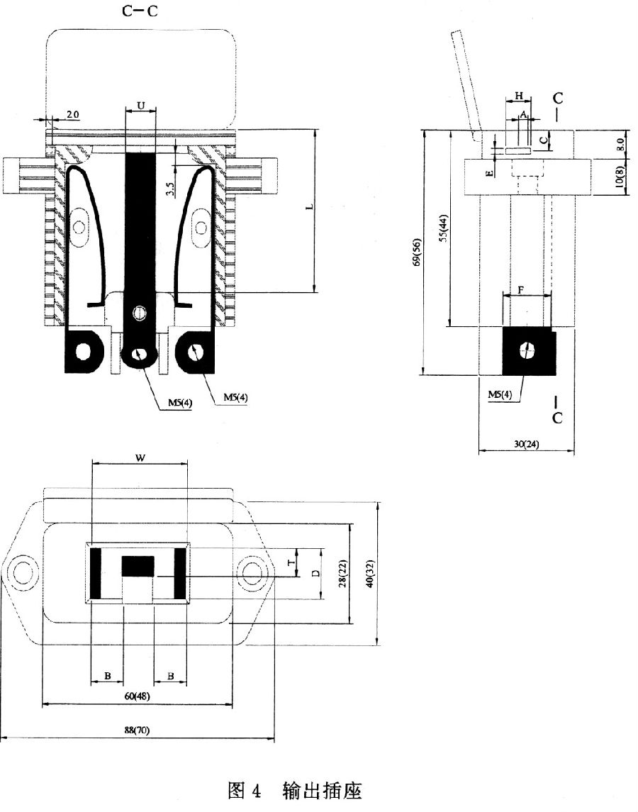
6.1 Through visual inspection 5.1.1, 5.1.3, 5.1.4 and 5.2.
6.2 Anti-rust (5.1.2)
Carry out the anti-rust test according to the requirements of Chapter 31 of GB 4706.1.
6.3 Pull-out force (5.3)
Maximum pull-out force: the sample is fixed as shown in Figure 5, insert the standard plug into the sample, the main weight is added to the weight (the latter's force is 1/10 of the former), the gravity of the standard plug and clamp, etc. The sum is equal to the maximum pull-out force shown in Table 2.
The unit is mm Figure 5 Pull-out force test device
Suspend the main weight in a way that does not subject the test plug to impact, allowing additional weights to fall on the main weight from a height of 5 cm. The plug should not be left on heavy objects.
Unipolar minimum pull-out force, the surface roughness Ra of the hardened steel gauge (bolt) is 2μm, the basic size is 0.2mm smaller than the specified bolt diameter, and the limit deviation is 0.01mm. Use this gauge to insert each corresponding In the sleeve, measure the force required when pulling out.
The sum of the force and the gravity of the gauge should exceed the minimum unipolar pull-out force specified in Table 2. This experiment is conducted after the maximum pullout test.
6.4 Insulation resistance and dielectric strength (5.4)
6.4.1 Insulation resistance (5.4.1)
Measure with a 500V megohmmeter.
6.4.2 Dielectric strength (5.4.2)
The voltage applied at the beginning of the test should not exceed 1/2 of the specified value, and then quickly increase to the specified value.
6.5 Temperature rise (5.5)
After energization, 1h below 32A, measured with melted particles, color indicator or thermocouple.
6.6 Cable compression force (5.6)
Use the cable with the largest (small) diameter that meets the requirements in Table 3, introduce electrical accessories, and press the cable with a crimping plate, but the core is not connected to the terminal, and then make a mark to fix the sample to the lever of the device shown in Figure 6 Above, the weight of the weight specified in Table 7 rotates at a speed of 1r/s. When the eccentricity and the fulcrum are at the minimum distance, the weight falls on the supporting surface. When the eccentricity and the fulcrum are at the maximum distance, gravity acts on On the electrical accessories, after 100 rotations, remove the sample to measure the displacement of the mark.
The unit is mm

Figure 6
6.9 Breaking capacity (5.9)
Follow the line shown in Figure 7 on the dedicated equipment. Fix the sample on the fixture, insert and pull out at a frequency of 7.5 times/min under 1.1 times the rated voltage and 1.25 times the rated current (the insertion and extraction are counted once), the separation speed is 8.0cm/s , The power factor of alternating current is 0.6±0.05. The number of tests per pole is 1/2 of the total number.
6.10 Normal operation (5.10)
Use 6.9 equipment and methods to insert and pull out at a frequency of 7.5 times/min. After every 500 times, wipe the latch of the electrical accessory with a dry cloth. After the test, it should be able to withstand the dielectric strength test of 6.4.2, but the test voltage is reduced by 500V.
6.11 Mechanical strength (5.11)
6.11.1 The impact test shall be carried out with a spring impact device complying with the requirements in Table 4.
6.11.2 The drop test is carried out as shown in Figure 8. Fix one end of the cable on the wall, hold the sample and level the cable, and then let it fall on the concrete floor. Do this 8 times in a row, each time rotating the cable 45° around the axis at its fixed place.
The unit is mm

Figure 7
6.12 Mechanical stress (5.12)
According to the torque specified in Table 8, after tightening and loosening with a screwdriver for 5 times, the screw nut should not be damaged that would affect continued use.

6.13 Creepage distance, clearance and penetration insulation distance (5.13)
By measuring whether it meets the specified requirements, the measurement method is in accordance with Appendix E of GB 4706.1.
6.14 According to the requirements of GB 2423.3, carry out a moisture-proof test. The sample is placed in the middle of the humidity box for 48h.
6.15 Heat resistance (5.15)
6.15.1 Place the sample in an oven at a temperature of (100 ± 5) °C for 1 h, and observe whether it has damage that affects the use.
The unit is mm
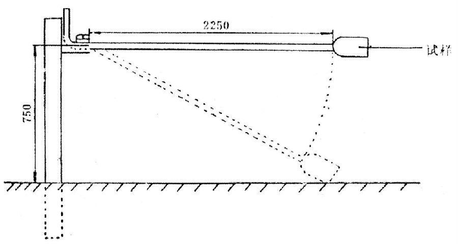
Figure 8
6.15.2 According to the equipment shown in Figure 9, the surface of the parts made of insulating material is placed in a horizontal position, and a steel ball with a diameter of 5mm is pressed against this surface with a force of 20N. The test is carried out in an oven. Its temperature: (125±5)℃ for live parts, (80±5)℃ for other parts, take out the steel ball after 1h, and the diameter of the measurement mark should not exceed 2mm.
6.16 Versatility (5.16)
The types, basic parameters and sizes of 16A and 32A electrical accessories are measured with vernier calipers with a division value of 0.02mm.
And can be common to each other.
6.17 Connection reliability (5.17)
Use a screwdriver to loosen the screws and check.
7 Inspection rules
7.1.1 Ex-factory inspection content includes Articles 4.1, 5.2.2, 5.2.3, 5.4, 8.1 of this standard.
7.1.2 The factory inspection method is determined according to GB 2828, as shown in Table 9.
Each product should be inspected for Class A failure. If a fatal defect is found in the whole batch of products, the batch of products will be judged to be unqualified.
The unit is mm
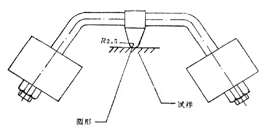
Figure 9 Ball pressure device
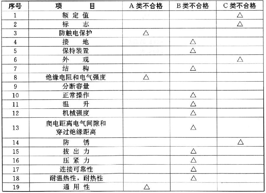
See Table 10 for the distinction between category A unqualified, category B unqualified and category C unqualified.
The sample is considered qualified only when the unqualified type A, unqualified type B and unqualified type C all reach the qualified quality level.
In the 19 items listed in Table 10, if any of them does not meet the requirements, it is considered that the item has not reached the standard requirements.
7.1.3 In the batch-by-batch sampling inspection, the sampling transfer rules in GB 2828 are adopted. When the batch quality is stable and reliable, you can switch from normal inspection to relaxed inspection, and vice versa, you should switch from normal inspection to stricter inspection.
7.2 In any of the following situations, the product shall undergo type inspection, and products without type inspection shall not be put into production.
a. When new products or old products are transferred to the factory for trial production;
b. After the formal production, if the structure, materials, and processes have changed significantly, which may affect the performance of the product;
c. Perform regular sampling tests on continuously produced products;
d. After the product is shut down for a long time, when it resumes production;
e. When the factory inspection result is significantly different from the last type inspection;
f. When the national quality supervision agency puts forward the requirements for type inspection.
Table 10
7.2.1 Samples for type inspection shall be randomly selected from a batch of (3) products.
7.2.2 If more than 2 products fail in one item in the type inspection, the batch of products is considered unqualified; if 1 product fails, another group of (3) samples should be taken to review the unqualified items If it is still unqualified, the batch of products will be unqualified, and the cause will be resolved until the test is qualified. The test applicant can submit two groups of products for testing at the same time.
8 Marking, packaging, transportation and storage
8.1 Logo
8.1.1 The electrical accessories shall have the following clearly marked durability signs.
a. Factory name or trademark;
b. Rated voltage and current;
c. Ground symbol;
d. Centerline symbol N.
8.1.2 The packing box should have the following signs:
a. Product name and specifications;
b. The name and trademark of the manufacturer;
c. Quantity and weight;
d. Standard code.
8.2 Packaging
8.2.1 Electrical accessories should be packed in cartons or plastic boxes and separated by corrugated paper or other materials.
8.2.2 The carton or plastic box should be packed in a dry wooden box, cardboard box or plastic box. The box should be protected from moisture or vibration
Measures.
8.2.3 The weight of each box (large box) does not exceed 25kg.
8.2.4 There should be a product certificate in the box.
8.3 Transport and storage
8.3.1 During transportation, rainwater and strong vibration shall be prevented.
8.3.2 Electrical accessories should be stored in a ventilated and dry room.